PSX & Multiple DCC Boosters
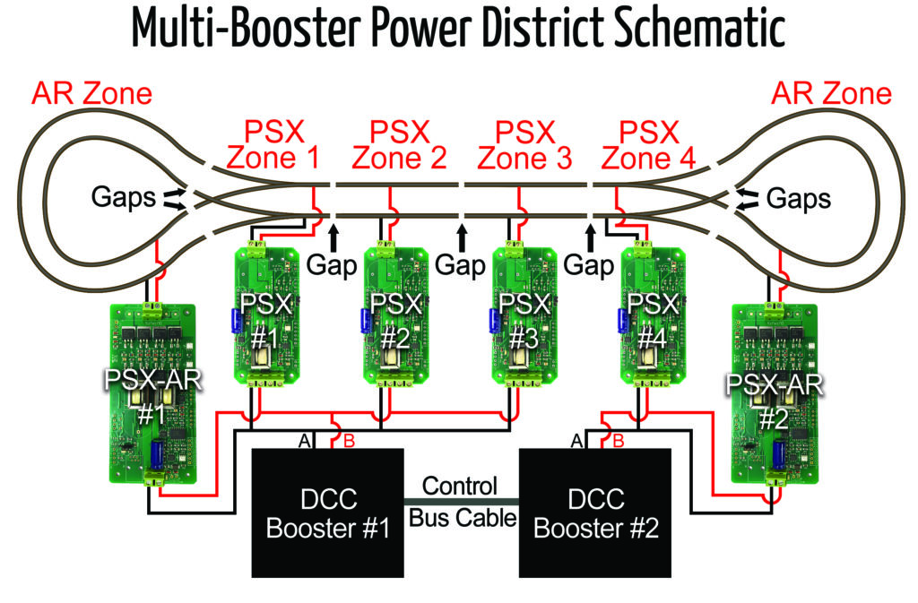
If you have two different boosters supplying power, then at some power district boundary, booster #1 will be powering one side of the district insulators and booster #2 will be powering the other.
When your engine crosses the boundary, there is a point where the front truck is connected to booster #1 and the rear truck is connected to booster #2 as the engine straddles the gap.
Since all wheels on one side of the engine are connected together (all wheel pick up), this essentially connects the output of booster #1 to the output of booster #2. If they are the same voltage, not much happens.
However, even a small voltage difference will cause the higher voltage booster to drive current into the lower voltage booster. This current can be large enough to trip the PSX, which is doing exactly what you want: it is preventing the high current from causing damage.
The NCE PB5 does not control its output voltage, which is dependent on the output of the power supply, so you cannot adjust it. The NCE PH-Power-Pro regulates its output voltage, so you can adjust it. Check page 15 in the Power Pro manual and find "Adjusting the PB105 DCC output voltage". Note that the NCE PB105 is the booster section of the PH Box (Powerhouse Pro system).
At the point where you are having trouble, pick one rail and place one lead of an AC voltmeter [the RRampMeter is a great tool for this] on the rail connected to booster #1 and the other lead on the rail connected to booster #2. This is reading the DIFFERENCE between booster #1 and booster #2. You don't need a really accurate meter; you are just going to make a relative reading. Typically, the meter will read something like 1.0 volts or so. Adjust the control on the PB105 [PH-Box] such that the reading on your meter is as small as possible. 0 is excellent, but something like 0.1 or less should do. A reading of 0.2 might be OK, but you will need to test it. Once the difference voltage is minimized, you should not have any trouble.