 July 11 2019
 Frog-AR Response Time and Current Limit
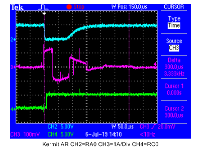
The response of the Frog-AR to a dead short circuit is shown below. The DCC source for this test is the NCE PB110A 10 amp booster, and the Frog-AR is triggered using a 13” wire connected from the DCC input to the Frog 1 output, essentially a short circuit across the booster output. Normally under this condition, the PB110A is easily capable of a 50 ampere output through the fault for a short time.
CH2 (cyan) is the “current setting exceeded” signal to the processor. CH3 (magenta) is the current drawn directly from the DCC booster. The current sensor is scaled at 100mV per ampere, so this trace is 1 ampere per division. CH4 (green) is the control signal to the frog polarity reversing output switch. 0V is ON and 5V is OFF (Note: the switch we are watching is turned off when the short is detected. The Reverse Polarity Switch is then turned on. There is no current showing this because the new output is in phase with the short, so there is no current flow). The time scale is 50us per division.
Remember the response traces were made with essentially a dead short across a 10 amp booster. Note that the Frog-AR (the magenta trace) has limited the current to roughly 1 ampere maximum even at the initiation of the short. The green trace shows the Frog-AR turns the output off within 10us. The cyan trace shows the short circuit current has dropped below the current setting (in this case 1 ampere) within approximately 80us. The magenta cursors show a span of 300us. The short circuit current is essentially 0 well before this time has expired.
The Frog-AR does not interact with circuit breakers for two reasons. First, it is fast enough that the circuit breaker does not have time to respond. Second, the current is limited during the short, so the current never exceeds the circuit breaker trip current.