UTP - Universal Throttle Panel Hints and Tips
by Don Fiehmann, Rev Feb 2005
Buy It Here
Download in PDF (399 kB)
Universal Cab Bus Throttle Assembly for NCE, Digitrax and Lenz and DCC systems
These notes are one of the evolving tip sheet on DCC subjects. The source of these tips comes from customer questions, personal experience, the internet and technical information. This note is on the installation and operation of the UTP (Universal Throttle Panel). The UTP will work with NCE, Digitrax, and Lenz DCC systems.
Walk-around Control
It is hard to believe that it has only been a few years ago that model railroaders were set free of the stationary throttle. Before walk-around train operation was like we were overlooking the layout from an Ivory Tower. Walk-around throttles and cabs allowed us to get close to operation of our trains. Radio and IR linked wireless throttles have even improved the ability follow the action.
The problem is wireless links are not 100% reliable. Batteries go low, transmission paths can be blocked and other things can happen. Most manufacturers of DCC systems recommend that plugin panels be placed around the layout to allow cabs and throttles to be plugged into the net when needed. Most system operate more reliably when connected with a tethered connection than with wireless connection. Programing is more reliable with a wired connection.
The popular way to connect DCC system throttles or cabs is using telephone types of connectors and cords. Another reason for the popularity of the phone type connectors is the low cost and the ease of replacing a faulty or broken connector. Even though DCC systems use different protocols (LocoNet, Cab Bus and so on) connections between the command station and cabs or throttles can use the same type of connectors and cables. This is why the UTP (Universal Throttle Panel) can be used with a number of different DCC systems.
UTP Features
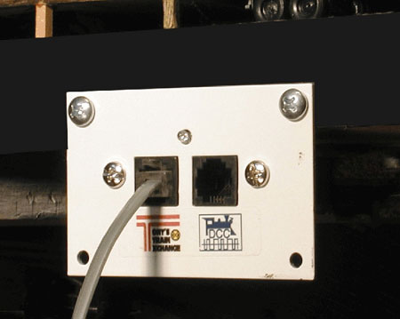
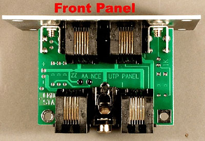
The UTP is designed to be a low cost unit to allow easy walk-around connections to be distributed in several convenient locations on a layout. The UTP comprises of a small printed circuit board with four RJ-12 connectors wired in parallel. Two connectors on the back are used to “daisy chain” the cable from the command station to more UTPs. The two connections on the front of the panel are used to connect to throttles and cabs. A metal panel is supplied to for mounting the UTP on edge of the layout of other convenient spot.
The Universal Throttle Panel is can be used with the (A) Cab Bus on NCE, (B) LocoNet on D igitrax and (C) Xpress bus on Lenz systems. The UTP will not work with the MRC Advance Prodigy system because it uses 8 wire cables.
Powering Option
The optional power connector allows additional power for the cab bus/LocoNet cable. This power is needed on DCC systems when the number of cabs or throttle exceed the limited power available from the command station. There can also be a problem with voltage drop on long cables. The telephone type of cable is used between UTPs is a light wire (#26 or #28 gauge wire). The wire size is OK for the signals but may cause a problem for power on long runs of 30 feet or more. Number 28 wire has a resistance of just under 2 ohms in 30 feet. For the current to flow both ways that’s 4 ohms. It would not take too many cabs plugged in to develop a high voltage drop. This is why added power is needed on long runs or systems with many cabs operating at one time.
Problems may show up as intermittent cab trouble when using many cabs or cabs at the end of long cable runs. Power can be added with a TTE-XNCE wall plug-in type power supply. This 12 V DC 1 amp unit has the correct plug for the back of the UTP.
Optional LED
There are a number of different wiring options for the optional LED. The LED can be installed as a status indication and /or provide an easy way to locate the UTP in a darken layout room.. The LED can be used to indicate power on the cab bus/Loconet cable. If connected to the rails near the UTP it will indicate power on the rails. A third option is to separately power the LED.
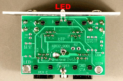
Installing LED
Any color LED will work with cab bus power. If you are using track power use a Bi-color red/green LED. A 3 mm LED will fit thru the hole in the front panel.
The LED should have the leads bent so the LED will fit thru the hole in the front panel and the leads go thru the two hole in the circuit board. The shorter lead on the LED goes thru the square hole next to the K on the board. (K for Cathode)
Install a 1K (1000) ohm 1/4 or 1/2 watt resistor in the two holes marked R1 and 1K on the component side, solder on the side marked R1.
Powering LED from Cab Bus
Two jumpers are needed to power the LED from the cab bus or XpressNet. Run one jumper from the LED + to the +connection above. Then run a second jumper from the — connection to the LED — connection. W ill not work with LocoNet (Digitrax)
Powering LED from the Track Power
Two wires are run from track power to the LED+ and LED — connections. (This application requires a Bi-color LED.) These two holes will take a #4 screw if you don’t want to solder the wires. OK with LocoNet (Digitrax).
Powering LED from an External Power Supply
A voltage source from 5 to 15 volts dc can be used to power the LED. Connect the positive wire to LED+ and the negative wire to LED — . OK with LocoNet (Digitrax)
Application Notes
1. Face Plate Grounding: Add a jumper to Y Y on the circuit board. This connects the front panel to the black wire.
2. External Power Supply: Cut the trace at Z Z on the circuit board. Install a 22 ohm 2 watt resistor at holes marked A A. Connect external power supply to holes marked (+) and ( — ). Install a wire to the hole marked COM from panel to panel.
3.Digitrax Battery Saver with command station in sleep mode: Add five diodes to D1,D2,D3,D4 and D5 as shown on the circuit board. Cut the trace at location X X on the circuit board. Install a wire to the hole marked COM from panel to panel.
Cables and Cabling
There are two options on cables. They are available made up in different lengths. Or you can make your own custom length cables. Cables are easy to make. Cables can be used for either the UTP to UTP daisy chain connections or for the UTP to handheld cab. Most of the handheld cabs and throttle use 4 wire cables and connectors. There are two sizes of connectors. The 4 and 6 wire connector or the smaller 4 wire that is used for telephone handset.
By making them yourself they can be cut to custom lengths. With a good crimper repairs to cable ends are a snap. I started with a cheap plastic crimper and found that it was good for making defective cables! A good cable starts with a good metal crimper! (The cost of a good tool is soon forgotten, but you will curse a cheap tool every time it is used!) These connector are the IP or insolation piercing type of connection and require a lot of pressure for the contacts to cut through the insulation. Most crimpers have positions to 1.cut, 2.remove insulation and 3.crimp. The crimper should be able to handle both 6 wire and 4 wire connectors.
Here is a chart that shows the different wire usage with different systems.
| Pin # | Color | NCE | Digitrax | Lenz | Lenz Panel |
| 1 | White | No Connection (Reserved) | Rail Sync | No Connection | |
| 2 | Black | Ground | Ground | Ground | “M” |
| 3 | Red | - RS-485 | LocoNet | - RS-485 | “B” |
| 4 | Green | +RS-485 | LocoNet | + RS-485 | “A” |
| 5 | Yellow | + 12 volts | Ground | + 12 Volts | “L” |
| 6 | Blue | No Connections (Reserved) | Rail Sync | No Connection |
Making cables
To install a connector start with a clean cut. Then skin back the insulation to expose the wires. Put a connector in the crimper and place the cable in the hole in the connector. The white wire goes to pin 1. Then squeeze all the way down. Most DCC systems require that the cable have pin1 to pin1 connections. Cords make for telephone service can be different. All DCC systems require the 1 to 1 pin connection (See drawing) except Digitrax. The Digitrax system can use either the pin 1 to 1, or pin 1 to 6 configuration. If you make all cables pin 1 to 1 you can’t go wrong for any system!
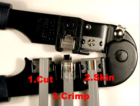
Crimpers perform three functions.
Installing UTPs
The UTPs should be installed in locations near the action. Yards and industrial areas are good candidates. If you use wireless cabs, locations where you have problems communicating would another good spot. The distance between UTP panels should be less than half the length of your cab cables.
Installing Cables
The cables should be twisted about 1 or 2 times per foot between UTPs. These cables should spaced at least 6 inches to a foot away from track power wires. If you have to cross over the track power wires do so at a right angle. These suggestions will minimize the crosstalk between the cab bus and track power.
Do not use staples to hold the cable in place as they may pierce the cable and short it.
Connect the UTPs together with about 1 to 2 twists per foot.
| Cab Bus Accessories | The following parts and supplies available from Tony’s Train Exchange |
| UTP/TTE | UTP/TTE Universal Throttle Panel with four RJ-12 connectors |
| TTE-XNCE | Plug-in 12 V DC power supply for UTP panels |
| M PP (??) | Assembled 6 wire Cables 5ft= MPP5, 10ft=MPP10, 15ft=MPP15, 20ft=MPP20. Longer cables available |
| M6C | Six conductor flat Phone Cable (for making your own cable) |
| M CC | Coiled 6 conductor. (Minimum 10 foot order) |
| M FF | Female (socket) to Female (socket) connector for 6 wires |
| M SP2 | Two way Splitter, 1 Male (Plug) to 2 Female (socket) connections |
| M PG | Crimp on RJ-12 six conductor plugs |
| M PC | Crimp Tool for 4 or 6 conductor plugs. |