 October 18 2022
 Do Bulbs and Snubbers Limit Current?
First, what about bulbs [ballast lamps], do they do any good other than to limit the amount of current flowing through a short?
Second, what about snubbers; do they dissipate these voltage spikes and current surges? I drew a blank on this one. But I did note you have a voltage spike surpressor diode built into the PSXX................Larry P.
Bulbs don't do much. Of course, it depends on the specific lamp, but let's look at an 1157 automotive tail lamp.
- It is rated at 26.88 watts at 12.8 volts.
- Current at these conditions is 2.1 amperes and an effective resistance of about 6.1 ohms.
- First thing to note is that if the bulb is lit, you have 0 volts on the track, so you absolutely cannot draw more than 2 amperes in your block during normal operation (practically it will be less than that).
- A normal incandescent lamp has an off resistance of about 1/10 of the on resistance.
- That would mean about 0.61 ohms.
- So normal track voltage of 14.5 (HO) and 0.61 ohms gives 23.8 amperes, about the same as an NCE 5 amp booster (27 amperes).
So not to much help. Of course, you could get a lamp that had higher off resistance to limit the current, but that will proportionately reduce the current available to operate in the block. Note also that the incandescent lamp has a thermal time constant in the 50ms or higher range and we are talking about spikes that last less than 20 ms (which is within the time range of a circuit breaker).
Snubbers will dissipate voltage spikes (although if you need to use them your wiring is inappropriate for DCC). They will NOT do anything about current spikes because when you get a short on the layout, you are also placing a short across the snubber. Technically, they would actually INCREASE the fault current when they discharge into the short, although this effect would be tiny.
More information: The output of a booster (simplified) is essentially a large capacitor connected to the track through a switch. When you get a short on the track, the only thing that limits the initial current is the resistance of the booster output switch, the layout wiring, and the short itself. The booster switch and the layout wiring are designed to have very little resistance because you don't want to loose voltage when you draw current to operate the layout. If you use a quarter, the fault resistance is generally less than 0.1 ohms. So, regardless of the source of the fault (engine derail, frog juicer, reverser, etc.) you are basically discharging a large capacitor through the fault. Worse, most accidents on the layout do not provide a nice clean turn on of the fault resistance. It is more likely, you get a fault that makes/breaks contact multiple time before settling down. This allows the capacitor to discharge then recharge and give another full strength pulse repeatedly. All of the above is valid except for the PSXX breaker. The difference is that when the current reaches the PSXX set trip current value, the PSXX rapidly (as in microseconds) changes the resistance of the output device to the value necessary to limit the current to the set value.
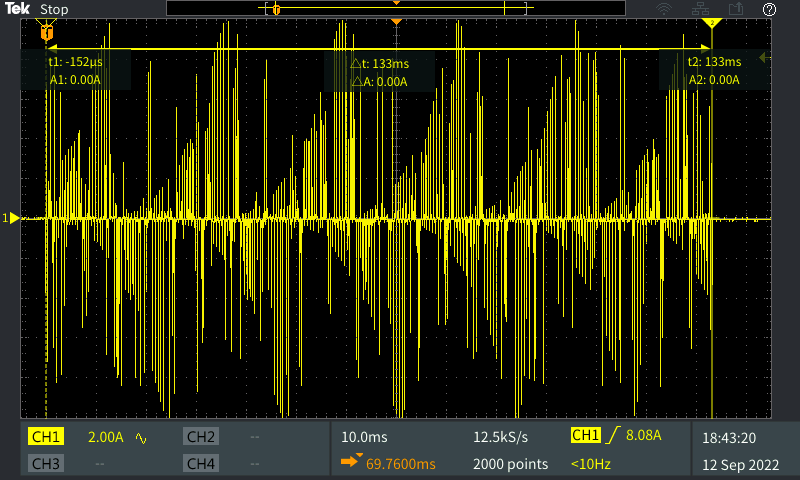
Visualizing the fault: Above is a 'scope display of a Digitrax DCS100 being shorted:
- Display is -10 amperes to + 10 amperes.
- Each spike is about 8us wide.
- This happens anytime the DCS100 is shorted.
- So, it does this while your shorting device (e.g. frog juicer, fault, reverser, etc.) is in the short condition.
- Note: that during this time, there is no DCC signal, so the entire layout is affected.
- Note: this test held the short until the DCS100 tripped off, the DCC would return once the short was removed.
The PSX and PSXX series both use TVS diodes. The PSX has them only on the input but the new PSXX has them on the input and output (this way it will absorb spikes whether the switch is open or not). A Voltage spike problem occurs when the short is removed, not when the short connects.
- The track likely does not having enough inductance.
- While that is probably true for the track itself the relevant inductance is also in the wiring, particularly if the wiring is not done using speaker wire or twisted pairs for the bus:
- Energy stored in an inductor is equal to {one half the inductance times the square of the current}.
- The short circuit current for some boosters can be 27 amperes or more.
- 27 squared is 729. 729 times even a small inductance can be a significant amount of energy.
- When the inductance discharges, the voltage will increase without limit until something conducts to take the energy.
- This is exactly how the spark plug on a small gas engine works, and the something that conducts is the air when a high enough voltage is reached to ionize the air molecules.
Another source of inductance it the power transformer in the booster power supply. There is definite inductance in the output winding of the transformer. Again, when you short the output, you get a high current through this inductance. When you release the short, the stored energy is discharged into your layout. This scenario may not apply to all booster power sources.
There is also inductance in a motor. We have not done any experiments as to the best placement of a TVS to protect the decoder from all of the above threats. Certainly across the motor is a good guess. In the circuit breaker is good since you might not need to equip all engines with TVS. I would be interested in what the failure rate is with the TVS across the motor. 0 would be a great result. On the other hand, TVS diodes are relatively cheap, and more than one protecting your decoder does no harm.
TVS is Transient Voltage Suppressor; a diode is will conduct in one direction, but block conduction in the opposite direction. However, preventing conduction in the reverse direction is not infinite. There is a voltage (the voltage rating of the diode) beyond which the diode will conduct in the reverse direction. Put another way, the diode acts as an insulator in the reverse direction but there is a voltage at which the insulation fails. Air is generally considered a good insulator, but it will conduct beyond a certain voltage (around 3 million volts per meter), which is why we have lightning storms. A TVS diode is simply a regular diode but with the reverse breakdown voltage crafted to occur at a specified voltage. A bidirectional TVS (which is what we would use in model trains) is simply two TVS diode place in series either anode to anode or cathode to cathode. The nice feature of the breakdown is that it is essentially instantaneous. This means that as soon as the voltage exceeds the rating, the diode conducts enough current to keep the voltage from increasing. TVS diodes are rated by the maximum voltage they will withstand without breaking down, the maximum voltage during breakdown, and the peak energy of a square pulse they can withstand without breaking down. Generally, the withstand voltage is in the part number. For model trains, 500 watt TVS diodes are usually used.
Sorry about that, apparently we got on a roll and couldn't stop..........Larry Maier