Adjusting The Throttle Response Curve
It’s easy to confuse the throttle response curve with acceleration & deceleration. The throttle response curve is the relationship of the motor voltage (throttle setting) to the speed step command sent by the command station. Acceleration and deceleration are the rate of change from one speed step to the next up or down.
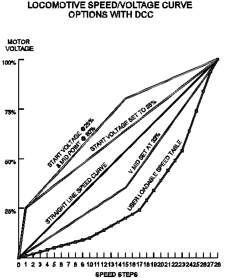
The Graph below shows the various curves that can be created using V-start and V-Mid adjustments or by programming the user loadable speed table for each discrete speed step.
Adjusting the Loco's Throttle Response Curve
The default motor voltage/speed curve is a straight line from stop to maximum speed. However, since locomotives don't really accelerate this way, DCC decoders let you alter this speed curve to simulate prototypical train motion. Let's look at the different ways to control locomotive speed and motion that are available with DCC. The chart above shows the default speed curve and how you can modify it by using V-start, V-mid & V-max.
MORE DETAILS
Discrete Speed Steps
Start Voltage
Mid Point Voltage, Max Voltage
Loadable Speed Tables
READ MORE ABOUT
Back EMF
Acceleration and Deceleration Rates
The Throttle Response Curve, Adjusting
Adapted from "Digital Command Control: The Wave of the Future", by Zana and A.J. Ireland.

