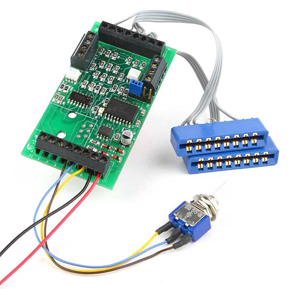
DCC Specialties Wabbits and CMOS Route Display
I have a number of Wabbits w/ feedback installed on my layout and they are working great. I would like to use the feedback opto-isolators to interface with a 4000 series CMOS logic circuit for route display with LEDs.
I would assume having a resistor between the + of my 9V power supply to pin 1 of J5 or J6 and pin 2 connected to the - (ground) of the supply would give the proper input to the logic circuit, from pin 1 and 2? Likewise for pin 3 and 4 for the Throw position.
What value of resistor should I use? Any help would be appreciated, and it looks like you have taken a lot of this into account in the Jack Wabbit. I'm also using Switch Master not Tortoise, so I don't have the relays on the machines. Thanks............Rick Graves
Rick: You are correct. Jx-1 and Jx-3 are + and Jx-2 and Jx-4 connect to ground. With CMOS logic, 24K should be fine. The coupler can drive as low as 1.8K @ 9V, but there is little need to go this low unless you are picking up a LOT of noise from your wiring.

