DCC Motor Control with Back-EMF and P-I-D
by Don Fiehmann
August 21, 2006
PDF Version (137 kB)
Progress Over the Years
The motors used in our locomotives have progressively gotten better over the years. Along with this the way we control these motors has continued to improve. The old rheostat gave way to solid state electronics with better control. Then came DCC with a decoder that had direct motor control. Decoders have continued the progress by improving the way they handle power to the motors. One of the biggest improvements has been the use of back-EMF to control motor speed. Back-EMF has been called cruise control for locomotives.
If you look through decoder manuals that have back-EMF control you may find something called “PID” or just “PI”. PID turns out to be a process control method that has been around for many years. It is a process designed to control things like temperature, pressure and speed. The PID process control method has been adapted in many of the back-EMF decoders for a more precise control of motor speed. The values for PID control are stored in CVs and can be “tuned” for precise motor operation.
Older decoders used a motor drive (PWM), pulse width modulation frequencies of about 30 to 200 Hz (cycles per second). PWM takes a constant like 12-18 v dc and drops to zero volts quickly and back to the higher voltage to get effective voltages between 0 and 18V. These frequencies were low enough to cause a hum or buzz in the locomotive. Most decoders today use a high frequency drive of 15kHz to as high as 43kHz. These frequencies are above the range of hearing and that is why they are called silent. This type of drive comes with many different names, depending on the manufacturer. One of the problems with the high frequency drive is slow starts. With these high frequency drives the motor tends to act like it is on dc power and is subject to stiction, where the motor does not start smoothly. The combination of back-EMF and the PID motor control can over come this problem.
PID?
The term “PID” got my curiosity up. I did a search on the internet and found a book by Simple Solvers that describes in simple terms just how the PID functions work. There was also an overview article about PID that could be downloaded from www.expertune.com.
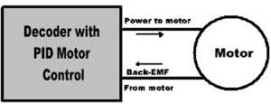
What I found out is that the PID control process is a little like a three ring circus. Each of these three items plays a part in the control process. For motor control you can think of PID as a black box with the output as the power to the motor and the input as the BACK-EMF from the motor.
For a smooth control the values of PID control can be adjusted or "tuned". For model railroading the way we have to check the results of tuning is to watch the reaction of a locomotive when we make a change to CVs that are associated with PID parameters. I found that one way to do some speed checking is using a track speed indicator like the Train Speed readout.
I dug thru many decoder manuals and web sites to try to figure out just how all fits into model railroad motor control. The back-emf controls run from a very simple turn on the function to some complex operations. Reading through the decoder manuals each manufacturer has a their own way of adjusting the PID parameters. Some of the decoder manufacturer’s have different names for PID. Some decoders do not use any implementation of PID.
What is missing is a explanation of just what all of the terms mean and what they do. Most decoder manuals have a way to “tune” the values fit your engine. Even if you have an engine with preset values, each engine is different, and some fine-tuning may improve operation. You may even want to have a different reaction than the pre-programmed values. You might prefer to have the engine slow as it starts up a grade.
Model Railroad PID
There is not a standard for the values used in the CVs. Nor is there a standard way to setup the CVs. For the most part tuning the values is a matter of determining CV values by trail and error. Some of the decoders either come with the back-emf feature turned off or they have a safe level of PID values pre-programmed.
Most of the decoders that use PID have a single set of values for the functions that are used over the total speed range. QSI on the other hand has four sets of PID values in their version 7 release. The QSI decoder switches between sets of PI D values depending on the speed step setting. Some decoders use CV10 to set a speed that turns off Back-EMF. CV10 is the only CV that is in the NMRA DCC specification related to Back-EMF. The other CVs are all setup by the decoder maker in the optional CV assignments.
In order to understand how the PID functions works we need to start with information on back-EMF and then on to an explanation of PID.
What is Back-EMF
A question I ask in some of my clinics is “What is the difference between a motor and a generator.” The answer is there is there is very little difference between a motor and a generator. If you apply power to the motor, the shaft turns. Conversely, if you turn the motor shaft, it will generate power, or a voltage in our case. When a decoder applies power to a motor and it starts to rotate. Since the decoder applies power as pulses (PWM) there is a time between pulses when no voltage is applied to the motor. During this time the decoder can “read” the voltage produced by the motor. If the motor slows, the Back-EMF voltage drops, if speed increases, the voltage also increases. This is how a Back-EMF decoder determines the speed of the motor and can sense any changes in motor speed.
The PID control process
Here is a brief description of the PID process. To start with you need to control speed. You send a speed command to the decoder. The speed setting is the input to the process and is called the “set point”. The decoder puts out power to the motor and the motor starts to turn. The decoder reads the back-EMF to determine how fast the motor is running. Once the motor speed nears the set point speed, the PID process starts to operate.
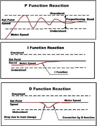
The “P” part of the process is “Proportional”. It sets up a speed band round the set point. This band allow some over and under speed near the set point. This is a little like how the thermostat in your house controls the furnace for the right temperature. The furnace continues to put out heat until the “set point”(thermostat setting) is reached. After this, some heat continues even after the thermostat turns the furnace off, this is overshoot. Most thermostats then wait until the temperature drops about 2 degrees below the set point before the furnace is turned on, this is undershoot. The “proportional band” is between the two levels. Digitrax information describes the “P” function like a spring. The higher the CV value the stiffer the spring!
The “I” part of the process is “Integral” action. This is a control of the difference between the set point and the center of the proportional band. This may not be the same due to system imbalance. The Integral action senses the difference between the set point and what the decoder uses for the center and tries to correct it.
The “D” part of the process is “Derivative” action. It looks for any change in the motor speed. When it senses a change, this function try’s to correct the change. This could be a locomotive that is starting up a grade with a string of cars and the load on the motor has increased, causing it to slow. The PID control “sees” this change and then applies a correction. The slow down could also be a bind in the mechanism or a tight spot in the track.
Some of the decoders only use the P and I (PI) functions and eliminate the D. QSI does little with the I function and more with the D function. This is one of the reasons why you need to read the manual for the decoder you are “tuning”. Can’t find the manual! Check the makers web site, most of the decoder manuals can be downloaded and printed. The QSI manuals have been updated for the new upgrade (Version 7) chips. Most of the web sites even have the discontinued decoder manuals available.
Setting CV Values
If the value in any of the CVs is too low, you have under correction, if too high, or over correction and you may get jerky reactions to speed changes. Most of the manuals have you tune the CVs using “program-on-the-mainline” programming. You set a value in a CV, then check the reaction by changing speed. You keep increasing the CV value until the reaction becomes unstable or jerky. Then change the CV setting back to the value that was stable. A procedure like this is used to set the CVs used for motor control.
One of the problems with Back-Emf control occurs when in a consist. W hen the first locomotive with Back-Emf starts up a grade, more power is applied to the motor. The second locomotive then cuts back its power. Then the second starts up the grade and increases its power, the first locomotive see a drop in the amount of “pull” needed and cuts back. This sets up a situation where the two locomotive keep changing power levels and you get an accordion like action between the two locomotives. Digitrax uses different setting when the engine is used in a consist.
There was some interesting comments on the internet on how to run helpers on a long train. The suggestion was to start up the grade and leave the front engine speed alone and control the pusher so the slack between push and pull stays in the middle of the train. One interesting side note is the prototype always put helper engines in the front of a passenger train. The reason is that if an engine were on the back pushing and the other engine pulling, somewhere in the middle of the train would be a car that was caught bouncing back and forth between been push and pulled. What car is in the middle of a long passenger train? The dining car of course!
Information from the decoder manuals on Back-Emf and PID
Digitrax
Digitrax calls their Back-Emf control “Scaleable Speed Stabilization”. They have a very good Application Note on setting up their decoder’s Scaleable Speed Stabilization.They use CV55, CV56 and CV57. CV57 is split so half controls its function as a single locomotive and the other half when in a consist. This note also includes instructions on adjusting these CVs.
QSI Industries
The new release level 7 (also the upgrade) of the QSI decoders has a very sophisticated four level speed control using Back-Emf and PID. Information on setting up the PID CVs is in the DCC Reference Manual version 4.0. Version 7 is the new upgraded chip available from QSI Solutions. A new page manual can be downloaded from QSI Solutions web site. The setup information can be found starting on page 170 to page 175. There are some good hints on tuning PID parameters. The CV values in these (upgrade) chips have been established by running a number of sample locomotives. As locomotive wear and due to manufacturing differences, some locomotive performance may be improved by re-tuning the CV values.
Lenz
Lenz has a document called “Getting the Most out of Back EMF Decoders” on their web site. They call their Back EMF control “Load Compensation”. The earlier decoder like the 1024 only have a single CV and bit to turn Back-EMF on. Here are the CVs used in the new Gold Decoder for Back-EMF control.
CV 9 Back EMF Repetition Rate (PWM)
CV50 Motor configuration
CV113 Minimum PWM value, control for motor types 4 or 5
CV114 Change duty cycle for motor type 4 or 5
See the decoder manual for more information on setting these CVs.
SoundTraxx Tsunami (products)
The new Tsunami has a number of CVs related to PID control. They are Kp, Ki, and Kd. There are two more that are used to control the length of time or widow when to sample the Back-EMF voltage. The information on these can be found in the manuals for the Tsunami. The Steam Sound User’s Guide on page 57 to 60 is information on setting up the Hyperdrive. In the Technical Reference on page 90 to 94 shows information about CVs 209 to 214 for the Advance Motor Control Features. All of these manual are downloadable from SoundTraxx.
LokSound
In the LokSound V3.5 users manual part 5.2.1 is a section on their load control. This is similar to their other decoders. They have CV54 to control “K”. The explanation makes it look a lot like “P”. CV55 is listed as parameter “I”. They also use CV 53 to set the voltage for top speed. There is no “D” CV listed. They have a listing of common CV settings available on their web site.
NCE
The D14SR decoder manual is typical of most of the NCE decoder when it comes to motor control. This line of decoder’s has Silent Running™ and Torque Compensation. There is a section in the manual on Fine tuning locomotive operation . It explains how to adjust CVs associated with starting characteristics. (No PID information.)
MRC
The instruction sheets for the steam and diesel decoders only show CV123 used to turn Back-EMF on or off. No information on CV settings other than the on and off.
Hints on Testing Decoders
The first, read the decoder manual before starting to do any adjustments. If you get things goofed up, most decoders have a way to return the CV settings back to the factory settings. For many decoders a factory reset is done by programming an 8 to CV8.
The way I test how well the Back-EMF works at low speed is to put my finger on the rails and stop the engine at speed step 1. The drive wheels should continue and slip on the rails with good Back-EMF operation. When you release the engine it should continue at the same speed and not speed up then slow down to the original speed. If it does speed up for a moment, something is over compensating and may need adjustment.
For very slow speed operations, try using 128 speed steps instead of 28 speed steps.
Reverse and forward trim can best be adjusted using something like the Train Speed device that can give speed in scale miles per hour. Train Speed has a speed readout and uses photo cells to detect engine speed in scale miles per hour.
When testing speed it is best to know the speed step that you are sending to the locomotive. Some cabs or throttles will have a read out for the speed step number, some only have a knob and it is hard to tell the exact speed step. The DCC Pocket Tester has a readout the will tell you the speed step number that is being sent to the locomotive.
When adjusting CV’s related to PID, CV3 and CV4 should be set to 0 for the fastest response time. After testing, CV3 and CV4 can be set back to the original values.
The Train Speed indicator and the DCC Pocket Tester are both available from Tony’s Train Exchange.