PSX with Photocell Detection
I finally got my bench work and track down and ready to hook up the photocell. I just received the CTI photocell and a PSX-AR from you guys. The photocell had no instructions and not sure how to install and wire it. It came with a resistor. Any suggestions?--------Thanks, Gary Spencer
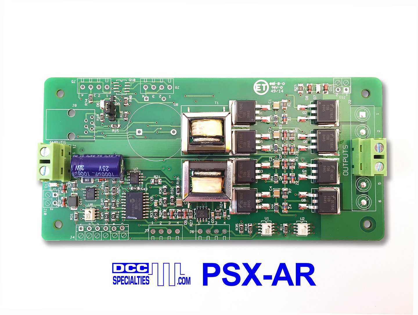
Simply mount the photocell between two ties at the location where you want the train to stop. We do this by using a #60 drill to make two holes in the roadbed spaced the same distance apart as the photocell leads. We use Digikey part number A460-ND to make a socket for use under the layout. You can also solder wires directly to the photocell leads. If you do this, heat shrink the leads, and you will need to drill the holes large enough to pass the solder joint with heat shrink on it, so try to keep the solder joint small. Once through the roadbed, twist the photocell leads into a twisted pair and connect them to J4-1 and J4-2 on the PSX. Either way is fine, the photocell is not polarity sensitive. Done.
Send an accessory ON command to accessory address 2043. When the phototcell covers, the breaker will turn off. An accessory ON command to accessory address 2042 will turn the breaker back on. These are the default addresses, and can be changed if you want. Remember, if you give the PSX a new address, the new address will be the on/off command, and the new address +1 will be the photocell arm command. The photocell calibrates the ambient light level when you arm it, so make sure it is not covered when you go to address 2043.