Digitrax DCC Hints and Tips Updated for 2013
By Don Fiehmann
Updated by Norm Stenzel 3/2/2013
Don Fiehmann, an avid model railroader and DCC user, drafted this for us circa 2004. Norm Stenzel, our resident Digitrax DCC expert, has updated it to reflect the evolution of the Digitrax DCC systems.
These notes are an evolving tips sheet on operating Digitrax DCC systems. The source of these comes from customer questions, personal experience, the Internet and Digitrax documentation.
Digitrax has been producing their popular DCC system since the 1990s. There are now three starter systems available from Digitrax DCC. On the low end is the all-in-one Zephyr Xtra, in the middle is the Super Empire Builder Xtra and on the top is the Super Chief Xtra. This family of products will all interconnect through LocoNet. LocoNet links the command station to boosters and the handheld throttles. Even the low cost Zephyr Xtra has a LocoNet connection and can be used with the handheld throttles. If you start with a Zephyr Xtra and later expand your system, the Zephyr Xtra can be used as an expansion booster. Digitrax also makes a long list of decoders for different scales.
The NMRA standard applies to the signals that are on the rails. In practice this means that it is up to the manufacturer to build a system to generate the signals. This is why you need to buy handheld controller, power stations (boosters) and other components by the same manufacturer. Since the DCC signal on the rails is standard, any manufacturer’s decoders must respond to this standard. This is why some parts of a system may not be interchangeable, but you can use a mix of decoders from any manufacturer.
Choosing a System
With the choice of three different starter sets the one that is right for you depends of how the system will be used. Things to consider include number of operators, scale and number of locomotives running. All three use LocoNet connections to allow use of handheld throttles. The throttles can be linked by tether, radio or IR. For the amount of power needed look at layout power requirements later in this document. Additional power boosters also connect to the LocoNet.
ZEPHYR XTRA (DCS51X)
For a small home layout the Zephyr Xtra will work and can run up to 20 addresses. The Zephyr is a stationary unit, but with the LocoNet you can add handheld throttles around the layout. The amount of power from the Zephyr Xtra is about 3.0 amps. This may limit the number of locomotives that can be run in your scale. On the positive side, the Zephyr Xtra is a full function programmer and can read back CVs using a program track.
The Zephyr X supports function outputs for F0 to F28. It can also be set up as a 3.0 amp booster if you upgrade systems. The Zephyr Xtra is the only system that has 2 novel JUMP ports which allow a DC power pack to run DCC equipped locomotives. One of the local clubs has obtained a Zephyr Xtra to determine if their existing DC layout wiring will work with DCC. A bigger system will be needed once converted. After conversion the Zephyr Xtra can then be used at the work bench to program decoders without interrupting layout operation.
SUPER EMPIRE BUILDER XTRA (DB150)
The Super Empire Builder X is a step up from the Zephyr Xtra with the ability to run up to 22 locomotives and throttles. It comes with the DB150 5 amp command station / booster. This system comes with a DT402 full feature throttle and has function outputs for F0 to F28. The Super Empire Builder Xtra does have one limiting item and that is that the DB150 has a “Write Only Programmer” and cannot read back CV values
SUPER CHIEF XTRA (DSC100/DSC200)
This is the top of the line system with the ability to support up to 120 locomotives and throttles from a control perspective. It is a good choice for large home or club layout. This system comes with a DT402 throttle and has function outputs for F0 to F28. The Super Chief Xtra has separate outputs for a “Read / Write Program Track”. The Super Chief Xtra is available with a 5 amp (DSC100) or 8 amp (DCS200) Command Station / Booster.
Digitrax Upgrade of Older Chiefs
Users of older DCS100s that cannot access functions 6 and higher can send their DCS100 to Digitrax for an upgrade. Cost for the upgrade is $35, which includes return shipping. Contact Digitrax for more information at digitrax.com.
Layout Wiring and System Setup
Layout Wire
Wire has resistance. The longer the wire the greater the resistance. Smaller wire has more resistance per foot. Resistance causes a voltage drop. The greater the current the more the voltage drop resulting in loss in train speed and dimming lights. It is advisable to keep the voltage loss to less than one volt. Nickel-silver rail is not a good electrical conductor and adds to the loss. Wire should be installed in parallel to the rails called a wiring “Bus” and a drop from the rails to the wiring at least every 6 to 10 feet. Here is a chart listing wire size, currents and lengths. A good source of wire is the speaker wire from the Radio Shack. Be sure to get the stranded wire.
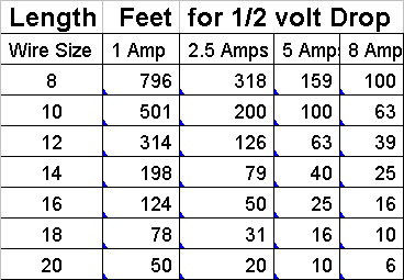
Chart for ½ volt drop. This would equal a 1 volt drop for a wire to the layout and back to the base unit.
To determine the voltage drop of an existing layout wiring you can use an RRampMeter. Put one end of the meter on the rails and put a load on the other end to get a reading under load. You can make a simple load from an automotive lamp. Measure the voltage with the load and then without the load to determine the amount of loss. The #1156 lamp will give little over a 2 amp load. A #1141 lamp is about 1.5 amps and the #912 lamp near 1 amp. The RRampMeter is a versatile handy tool to have for testing and monitoring the electrical system of a layout.
Blocking the Layout
With only two wires connected to the main track connection a single short circuit will shut down the layout. To prevent a single short from shutting down the entire layout, the layout should be divided into sections known as power districts and sub districts. A power district is a section of the layout that is powered by a single power booster. A subdistrict is a section of track or block that has a separate circuit breaker. Another type of block or subdistrict is a reversing loop or reversing sections like a turning wye. DCC Specialties make the most popular DCC circuit breakers and reversers.
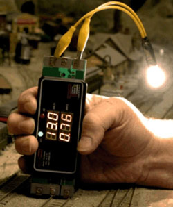
Checking voltage drop with an RRampMeter. Automotive lamp used as a load.
Common or House Wiring
There are two ways to wire to rails of a layout. One is the “House Wiring” where two wires are used to feed each block, called house wiring because it is like the wiring in your home. Digitrax recommends house wiring. The other is “Common Wiring”, sometimes called “Common Rail” wiring. Most modelers use house wiring, but the common wiring will work with DCC.
There is one rule-of-thumb that applies to either style of wiring. Only one item can be wired in common. For common wiring the return wire is the common item. With house wiring you can use a common transformer. But even with house wiring it is still best to use separate transformers for each of the command station / booster and each booster.
Layout Power Requirements
Digitrax offers either a 5 amp or 8 amp command station / booster. The 5 amp is ample power for most small to medium size layouts in N through S scales, this will even work well with newer O scale locomotives. I’ve run 2 newer O scale locomotives on a 3.0 amp Zephyr Xtra system. For older O scale and G scale the 8 amp unit should be used.
The 5 amp power booster should handle the requirements of most layouts. To determine if you will need additional power here are some figures you can use for planning.
To find out whether the maximum current of the system used is sufficient for the supply of your model railway system, simply add up the power consumption of all locomotives running at the same time as well as that of all other items that consume power. The following approximate values can be used to determine layout power requirements.
If you have a consist, add the number of powered locomotives in the consist.
Running locomotives - depending on gauge and attached load, the power consumption ranges from 200 mA to 2000 mA. Calculate per locomotive 300 mA for N gauge, 600 mA for HO gauge and 2000 mA for larger gauges. This ensures that you still have some reserve left.
Standing locomotives - not illuminated 5 mA, illuminated approx. 50 mA for each bulb. 15 mA for each LED, illuminated passenger cars - each bulb approx. 50mA.
If the calculated sum exceeds the maximum current available from the DCC booster you need to split your layout into multiple power districts and install additional DCC boosters to provide power for each of these power districts. The Digitrax DCC family includes two expansion power booster models depending on the current needs and scale of your railroad. Remember to plan for the future.
There are two power boosters available from Digitrax plus the Zephyr Xtra. The Zephyr Xtra is rated at 3.0 amps and boosters are available at 5 or 8 amps. Output voltage of the Zephyr Xtra is fixed at about 13 to 14 volts. The 5 amp power booster is the most common and the 8 amp power booster should be reserved for G and O scale. Some of the boosters have a three position SCALE switch to set the output voltage. The positions are N for 12 volts, HO for 15 volts and O/G for 20 volts. Regardless of your scale you should use the lowest setting that works. There is also an internal voltage adjustment on some of the boosters. Check your manual for more information on voltage settings.
Transformer Requirements
The command station and power boosters require a transformer for power. If a transformer is used that has an amp rating less than the output of the power booster there may not be enough power to trip the over-current protection. For most applications a 16 to 18 volts AC transformer works best. Digitrax specs call for an AC voltage input of 12 to 20 volts or a DC input of 12 to 28 volts. Exceeding these voltages can cause damage. Current ratings should be the same or slightly higher than the booster output.
| COMMAND STATION / POWER BOOSTER | SUGGESTED TRANSFORMER |
|---|---|
| Zephyr Xtra (DCS51) | Supplied with the Zephyr Xtra |
| Super Empire Builder Xtra DB150 (5 amp) | P515 16VAC 5 amp for HO to On3 |
| Super Chief Xtra DSC100 (5 amp) | P515 16VAC 5 amp for HO to On3 |
| Super Chief Xtra DSC200 (8 amp) | XFR10 18VAC 10 amp for O and G scale |
Circuit Breakers and Accessory Decoder Wiring
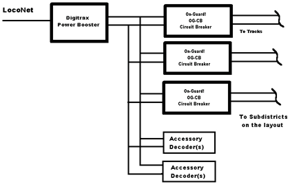
One of the most common causes of short circuits is running into a turnout that is set the wrong way. If you power an accessory decoder from the rails the short will cut the power to the decoder and you cannot throw the switch to clear the short. This situation can be avoided by wiring the power directly from the power booster to the accessory decoder and using a separate circuit breaker for the track. A short circuit will trip the circuit breaker while the accessory decoder continues to receive power via the booster and allows you to throw the switch to clear the short.
Even without accessory decoders using circuit breakers will allow sections of the layout to continue to operate with a short circuit in one of the other sub districts. DCC Specialties PowerShield PSX and OnGuard OG-CB circuit breakers are most popular options. There is also PSX-AR and an OnGuard OG-AR switching the polarity for reverse loops which both have an integrated circuit breaker.
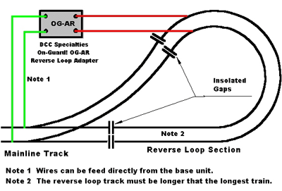
Reversing Loops
A reversing loop is a section of track that allows the train to turn around and reverse directions. Reverse loop wiring and operation is much simpler with DCC than DC. On DC the reverse loop was wired so that you could flip the polarity of the mainline while the train was in the loop. On DCC it is done the opposite way. With DCC the polarity of the train can be reversed under the train while it is in the loop. Polarity can be automated with a reverse loop adapter. The PSX-AR and the OnGuard Reverse Loop Adapter (OG-AR) are solid state electronic devices. Two wires are connected to the mainline or power booster and the other two wires are the only connection to the isolated loop. When the metal wheels cause a short either entering or leaving the loop the adapter automatically switches the loop polarity.
Output Track Status Light
Track status light on the command station/booster is normally an amber color. If it is either shifted to red or green it can mean one of two things. Either a fault in the output of the booster or you have run an engine using the 00 address feature.
Caution: Analog (DC Ops)
Address: (00) We do not recommend!
If you put a non-decoder equipped engine running on address “00” on the layout and set the speed high it can distort the DCC signal. To fix this you need to select address 00 and turn the throttle to zero speed setting for that address. Then dispatch address 00. If you had a large layout with lots of engines you will find that this feature can slow response and be sluggish.
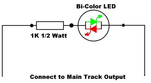
You can use a bicolor LED to monitor the status of the track power. Here is a simple circuit that will give you the information. Normally it is a yellow/amber, a distinct red or green indicates a DC output bias and may be indication of a malfunction.
LocoNet Cables
If you need to make or buy LocoNet cables to run from the base units to remote locations on the layout they should be correctly wired. Correct wiring has the same wire connected to the same pin on both ends of the cable. The connectors are 6 pin modular phone type connectors and the supplied cables have all 6 wires connected. If you buy cables be sure they are the 6 pin type. If you make your own be sure to use a good quality crimper that will handle 6 pin connectors. Some cheap crimpers don’t apply enough pressure to adequately crimp the wires to the pins. The cost of a good tool is soon forgotten, the problems with a cheap tool linger on.

Correctly connected ends for use with Digitrax DCC systems.
Parts to make your own cables are also available along with a crimper. The UP5 universal throttle panel is also available that provides additional throttle connections around the layout. The UP5 has two RJ12 connectors in the front for connecting two throttles and three in the back to allow you to “daisy chain” to the next UP5.
You should not connect the command station or power station to any non LocoNet device even if other devices use the same connectors. The fact that the connectors are similar does not automatically mean that the device is designed to work with Digitrax. This is true even if you are dealing with other model railroad DCC control systems.
Digitrax Mobile Decoders
Digitrax supplies decoders for most scales. The decoder part number is used to define the model and tells a lot about the decoder’s use and features. Starting with the 4th generation decoders here is some information on the code used.
Start with the decoder ID “DN163K2". They always start with a D for Digitrax.
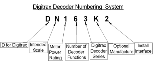
The next character is the scale. In this case the N is for N scale.
The third is the motor current rating. The number is one digit and in this case is 1.5 amps, but rounded down to a single digit.
The next digit - a 6 - is the number of functions available on the decoder. The fifth character is a series designator and may run from 0 to 9.
The next two characters are optional. In this example the K is for Kato and the 2 is the second style for Kato or interface used.
For a more complete definition see the Digitrax Mobile Decoder Manual. This manual is kept up to date and available from Digitrax or a free download over the internet from the Digitrax website. This website has the manuals of present production and most of the out of production equipment.
Just because a decoder is intended for a one scale does not mean that is the only scale that it will work with. I’ve seen N scale decoders used in an On3 Shay. Why? Because it fits! The decoder's amperage rating is what’s important not the scale.
Programing with Digitrax
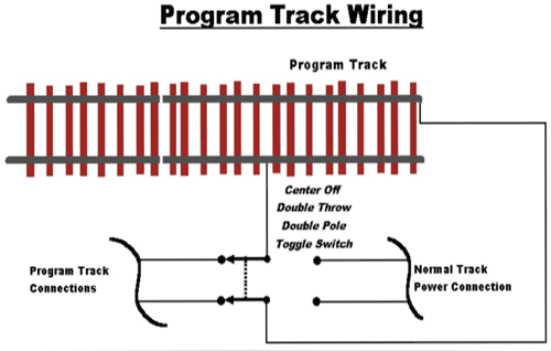
Program Track
The Zephyr Xtra and the Super Chief Xtra have outputs for a program track. This track can be a siding off the mainline. This section of track MUST BE ISOLATED with gaps on both rails. If you use a center off toggle switch the program track can be setup to select the track for programming or use for normal operations. With the center off the track can be used to put equipment on the rails without affecting operation or shorting out the rails.
The many sound decoders require more startup power to charge the capacitors than the programming outputs were designed for. This can cause a problem programming on the program track. If you have a problem, the DCC Specialties, PowerPax can fix it. The PowerPax is an adapter that is wired in between the command station and the program track. The PowerPax is guaranteed to fix this problem.
Decimal or Hex
In the early days of DCC systems commonly used hexadecimal notation for programming decoders. Thankfully this is no longer the case. All current Digitrax production uses regular decimal notation for programming. The Digitrax Decoder Manual gives CV values in both decimal and hex (hex is short for hexadecimal) so that folks with older equipment can still use the information. Knowledge of the hex and decimal numbering system can be a big help when you start setting up some of the special lighting or sound settings CVs. The values stored in a CV runs from 0 to 255 (0 to FF in hex). There are conversion charts available to convert from one numbering system to any of the other number systems. There is a decimal to hex chart in the back of the Digitrax Decoder Manual.
DCC or DC Settings
Bit 2 of CV29 permits some decoders to operate when DC is on the rails. This bit should be left off unless you have a real need to operate between DCC and DC. Leaving this bit off can reduce the possibility of runaways. Some decoders do not support DC operation. Check with the decoder manual.
| Bit | Weight | Function (When on) | Purpose |
|---|---|---|---|
| 0 | 1 | Normal Direction of Travel (NDOT) | To correct direction problems so forward is forward. Reverses the norm al direction of travel. |
| 1 | 2 | 14 or 28/128 speed steps | Sets use of 14 or 28/128 Speed Steps. Should be on unless you have an old decoder(14 speed step is obsolete and rarely used) |
| 2 | 4 | Power Source Conversion | Allows the decoder to operate on dc or DCC. Not supported by all decoders. Best left off. |
| 3 | 8 | Advance Decoder Acknowledgment | This is a feature in some newer decoders Leave this bit off unless you have the function. |
| 4 | 16 | Use Speed Alternate Table | Used for speed matching. Leave off unless you set up the speed table at CV67 to CV94. |
| 5 | 32 | 4 Digit Address (Off for 2 digit) | Sets 4 digit addressing. (2 Digit in CV-3 and 4 digit in CV-17 & 18.) |
| 6 | 64 | Reserved for Future use | Not used at the present time. |
| 7 | 128 | Defines Accessory Decoders | On if an accessory decoder/Off for mobile decoder. |
Addressing vs. Other Systems
The Digitrax system used addresses 1 to 127 as a two digit address and 128 to 9983 as four digit addressing. Address 00 is used to operate a single locomotive without a decoder. We recommend not using the “00” address. There are some address ranges that can be setup in other DCC systems that may not work on a Digitrax system. Addresses from 9984 to 9999 are not addressable with Digitrax systems. Some systems can setup address 0001 to 0128 as four digit addresses. This range of four digit address is also not addressable with the Digitrax systems. Problems with these address ranges only occur when locomotive decoders have been setup with non Digitrax systems.
Another area of addressing conflict is the two digit addresses and the addresses used for consists in CV19. A decoder cannot tell the difference between a two digit address and a consist address of the same number.
Four Digit Addressing
Most systems automatically setup 4 digit (long) addresses. These systems put the correct values in CV17 and CV18 based on the locomotive address. CV29 bit 5 (weight 32) also needs to be set for 4 digit addresses. All Digitrax DCC systems will automatically set CV17 & CV18 for the 4 digit address.
If your system does not automatically setup 4 digit addressing, here is a way to do it manually. The basic idea for this came from a QSI manual. The following way uses a calculator.
A. Start with the locomotive address and divide it by 256. Sample 4449 ÷ 256 = 1set 7.3789
B. Take the whole number (17) and add it to 192. Sample 17 + 192 = 207
C. Program the value (207) in step B is into CV17.
D. Multiply the whole number from step A by 256. Sample 17 X 256 = 4352
E. Subtract the locomotive address from the computed value in step D. Sample 4449 - 4352= 97.
F. Program the value (97) in step E is into CV18.
G. To activate 4 digit addressing a value of 32 (bit 5) needs to be added to CV29.
Consisting
Consisting or MUing (multiple unit) is the ability to run more than one locomotive together as a single unit. Three methods are available: basic consisting, universal consisting, and advance consisting. Basic consisting is addressing more than one decoder with the same address. With universal consisting the command station keeps track of the locomotives in a consist. The advance consisting is a newer way and uses CVs in the decoders to control the consist. The Digitrax systems can setup any of these type of consists.
With the universal type of consist the system can only run as many locomotives in the consist as there are available slots in the command station. More than 4 or 5 locomotives in a universal consist sometimes can slow down the reaction time of each of the consisted locomotives. Any functions are controlled by entering the locomotives number and using the function keys. The lead locomotive number is used for the consist number. With universal type of consisting the base unit sends out a separate comm ands to each locomotive for each change in speed or direction. When you enter a locomotive number and the locomotive is headed in the reverse direction from the other units push the direction key after entering the address. This tells the system to send this locomotive commands that are in reverse of the other units.
The advance method uses CV19 in each locomotive in the consist to hold the consist number. Any value in CV19 other than zero tell the decoder it is in a consist. Advance consists use the 1 to 127 address range. This is the same as the two digit addressing range. A conflict can be setup if you use a 2 digit locomotive address the same as a consist address. When in a consist the decoder will not respond to any speed ordirection at its normal address. A value of 128 is added to CV-1 9 when a locomotive is reversed in the consist. In a consist with the an address of 10 in CV19 a locomotive in reverse would have a value of 138 in CV19. There is a group of CVs that allow even more control of features while in an advance consist. CV-21 to 24 are used for these controls.
Programming on the Main Track
Programming on the main track is sometimes referred to as “Ops Mode Programming”. This allows you to change the value in a CV while out on the mainline. Functions like lighting, sound levels, acceleration/deceleration rates can be changed on the fly while operating a locomotive. The change will only apply to the address shown in the display. With a little practice you will appreciate what this feature can do for you in train operation. The value in a CV cannot be read back in Ops mode.
Operation with the Digitrax DCC Systems
Function Keys
The Zephyr Xtra, Super Empire Builder Xtra, and The Super Chief Xtra all can control functions F0 to F28. The DT402 Full Feature Throttle can access F0 – F28. The UT4 Utility Throttle can access F0 – F12.
The SoundTraxx Tsunami and QSI sound decoder use the function keys higher than F8. Below is a sample of the function keys and actions. Functions can be remapped if you need a function that is not in the range your system.
| Function Key | Typical Function | Tsunami Steam* | Tsunami Diesel* | QSI Steam* | QSI Diesel* |
|---|---|---|---|---|---|
| F0 | Head/Backup Light | Head/Backup Light | Head/Backup Light | Head/Backup Light | Head/Backup Light |
| F1 | Bell | Bell | Bell | Bell | Bell |
| F2 | Horn/Whistle | Whistle | Horn | Whistle | Horn |
| F3 | Short Whistle | Short Horn | Coupler Sound | Coupler Sound | |
| F4 | Steam Release | Dynamic Brake | Steam Blower | Fans | |
| F5 | Function F5 | Function F5 | Dynamic Brake | ||
| F6 | Function F6 | Function F6 | Doppler/Startup | Doppler/Startup | |
| F7 | Light Dimmer | Light Dimmer | Brake Squeal | Brake Squeal | |
| F8 | Sound Mute | Sound Mute | Sound Mute | Sound Mute | Sound Mute |
| F9 | Water Stop Sound | RPM + | Cruise/Shutdown | Cruise/Shutdown | |
| F10 | Dynamo | RPM - | Short Air Let Off/Pop Off | Speed Read out | |
| F11 | Brake Squeal | Brake Squeal | Short Air Let Off/Boiler Blow Down | Number Board | |
| F12 | Coupler Sound | Coupler Sound | Short Air Let off | Hazard/Cab Light |
* Note: The above chart is subject to change depending on the type of locomotive or decoder.
DCC Documents
DCC system and decoders all come with manuals or information sheets. When you buy DCC products you get a receipt from the supplier. All of these documents should be retained. You may need a receipt to prove when you bought a device when getting something repaired under warrantee. Manuals are needed for reference, like when a decoder gets amnesia and needs to be reprogrammed. It is a good idea to write down the programing of a decoder’s CVs and keep the information with the decoder manuals. Even though many of the manuals are now available over the internet in time they get obsoleted and can get removed. Digitrax does a good job of keeping manuals of obsolete equipment on their website, many others do not.
Sources of Help
There are ways to get help or have questions answered. One of the best is to join the Digitrax Yahoo group. The Digitrax Yahoo Group Chat list has thousands of members that can answer almost any questions you have. If you monitor the group you will find a lot of answers and many suggestions. Another source is Digitrax. If you still have questions after reading the operating manual, you can contact Digitrax at:
[email protected]
850-872-9890
Digitrax INC.
2443 Transmitter Rd
Panama City, FL 3240